 |
|||
|
|
|||
|
Page Title:
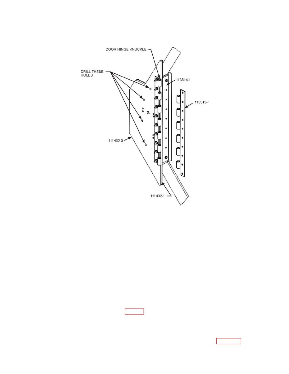
Figure 24. The correct Door Hinge orientation. |
|
||
| ||||||||||
|
|
 II106700-5
Rev. B
Page 41
b. Position the Front Side Cab Armor onto the side of the cab and secure the hinge
bracket to the door pillar using four bolts (5/16 18 x 1.500 LG). Be sure it is tight,
as this provides positions for other fasteners.
c. Insert a drill bushing into the hole (X4) and match drill four 3/16-in. pilot holes.
d. Remove the four mounting bolts securing the Front Side Cab Armor Plates to the
Door Pillar and remove the Armor Plates from the vehicle.
e. Using a drill and a 17/32-in. drill bit, drill through the four pilot holes.
f. Install four Rivnuts [3/8 16 (AVK)] into the four holes drilled into the cab (Use the
Rivnut Installation Tool, See Table 2).
g.
Install the existing clearance light gasket onto the amber clearance light, feed the
clearance light wire through the appropriate hole in the Front Side Cab Armor Panel
(P/Ns 111432-1 and 111432-3). Secure the amber clearance light onto the armor panel
using four bolts (3/16 - 24 x 1.250 LG) and four nuts (3/16 - 24) (See Figure 25).
0039 00-51
|
|
Privacy Statement - Press Release - Copyright Information. - Contact Us |
