 |
|||
|
|
|||
|
Page Title:
HEMTT C4ISR MOUNTING HARDWARE KIT INSTALLATION |
|
||
| ||||||||||
|
|
 II111450-1
Rev. A
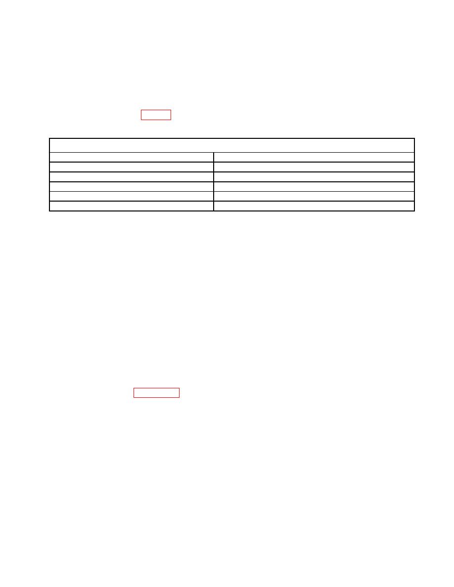
2.1 EQUIPMENT AND MATERIALS
The equipment and materials required to install the C4ISR Mounting Hardware Kit onto the
HEMTT are provided in Table 1.
Description
Part Number
Automotive General Mechanics Tool Kit
SC5180-90-N26
1/2-in. Drill
Commercially Available
9/32-in. Drill Bit
Commercially Available
Ball Peen Hammer
Commercially Available
Cold Chisel
Commercially Available
NOTE
These Installation Instructions will provide the illustration directly
after that installation callout, and the text will be on either the
same page or the facing page, where practical. All necessary
information, torque values, tool numbers, and materials used will
be provided so that the unit can be assembled without reference
to another part of the installation instructions.
a. Before beginning the assembly of a part, remove all corrosion-preventative
compound (if any) and any accumulated foreign matter.
b. All nuts, bolts, and screws used in the installation of the Kit must be coated with
Loctite 242 thread lock adhesive and tightened to standard torque values, unless
otherwise stated. The locknuts supplied with the Kits do not require Loctite 242.
A list of standard thread / pitch sizes and the corresponding torque values are
provided in Appendix A.
c. Inspect the Rear Cab Armor Panels, P/N 106724-3 / -4 for welded studs. If the
Panels contain welded studs, perform the following procedure:
1. Remove all of the welded studs from the Rear Cab Armor Panels,
P/N 106724-3 / -4.
2. Suggested stud removal process: Use a ball peen hammer and medium-
sized cold chisel. Align the chisel's edge against the base of the stud where
the stud adheres to the Armor Panel. Dislodge the stud using repeated
hammer blows on the chisel until the stud is freed from the Armor Panel. If
one is available, an air chisel may be used to remove the studs.
3. Prime / paint any exposed bare metal after the stud is removed.
The installation skill level required to complete the installation of the Kit shall be MOS 63S,
Heavy Wheel Vehicle Mechanic.
0040 00-10
|
|
Privacy Statement - Press Release - Copyright Information. - Contact Us |
