
TM 5-3990-263-13&P
0005
OPERATION - Continued
7
8
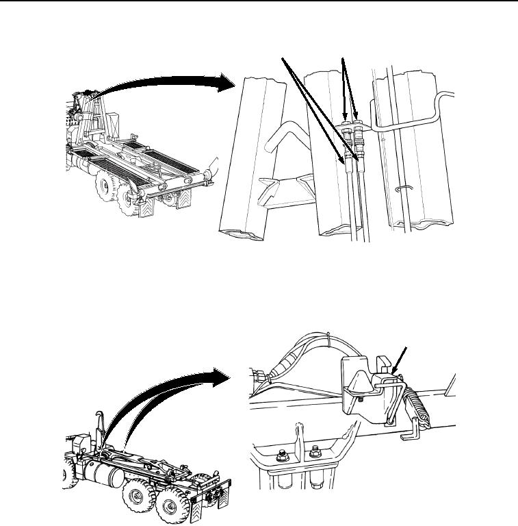
Figure 4.
Stowing Hydraulic Hoses.
6.
If the BAP is loaded with bridge bay, ensure all bridge latches are secured. Refer to TM 5-5420-209-12 or TM
5-5420-278-10.
7.
Ensure BAP hold-down locks (Figure 5, Item 9) are in the auto engage position (handle pushed in).
9
SHOWN WITHOUT BAP INSTALLED
FOR CLARITY
Figure 5. Setting BAP Hold Down Locks.
8.
Back up vehicle so at least 5 ft. (1.5 m) of clearance is available behind vehicle for loading the BAP. Refer to
TM 9-2320-435-10 or TM 9-2320-425-10.
03/15/2011Rel(1.8)root(opusualwp)wpno(O01054)

