
TM 5-3990-263-13&P
0031
CORRECTIVE ACTION - Continued
P2
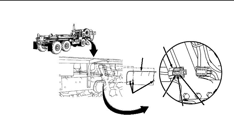
ACCESS
COVER
THUMB
POSITION
SCREWS
2
POSITION
POSITION
4
3
Figure 7. Connector P2.
8.
Place negative (-) probe of multimeter on position 35 of digital controller wiring harness connector
J4 (Figure 6).
9.
Place positive (+) probe of multimeter on position 3 of digital controller wiring harness connector
P2 (Figure 7). Check multimeter for continuity.
10.
Place negative (-) probe of multimeter on position 33 of digital controller wiring harness connector
J4 (Figure 6).
11.
Place positive (+) probe of multimeter on position 4 of digital controller wiring harness connector
P2 (Figure 7). Check multimeter for continuity.
12.
Place negative (-) probe of multimeter on position 5 of digital controller wiring harness connector
J3 (Figure 6).
13.
Place positive (+) probe of multimeter on position 1 of WINCH OUT solenoid connector
(Figure 6). Check multimeter for continuity.
14.
Place negative (-) probe of multimeter on position 35 of digital controller wiring harness connector
J3 (Figure 6).
15.
Place positive (+) probe of multimeter on position 2 of WINCH OUT solenoid connector
(Figure 6). Check multimeter for continuity.
a.
If continuity is not present at one or all of the readings, repair or replace digital controller
wiring harness. (TM 9-2320-435-10 or TM 9-2320-425-10)
b.
If continuity is present for all of the readings, proceed to next Malfunction.

