
TM 5-3990-263-13&P
0046
REMOVAL - Continued
NOTE
Perform Step (4) if grease fitting is damaged.
4.
Remove grease fitting (Figure 1, Item 8) from shaft (Figure 1, Item 6).
END OF TASK
CLEANING
Refer to General Maintenance Instructions (WP 0038) for general cleaning instructions.
END OF TASK
INSPECTION
Refer to General Maintenance Instructions (WP 0038) for general inspection instructions.
END OF TASK
INSTALLATION
NOTE
Perform Step (1) if grease fitting was removed.
1.
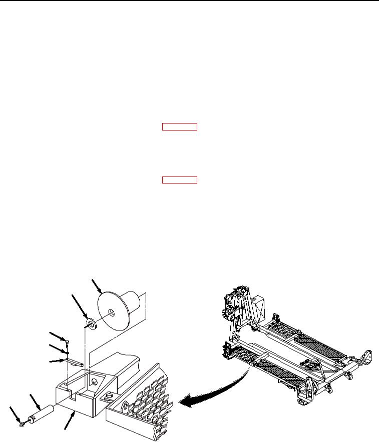
Install grease fitting (Figure 2, Item 8) in shaft (Figure 2, Item 6).
5
7
1
2
3
6
8
4
Figure 2.
Front Roller Assembly Installation.
2.
Install front roller (Figure 2, Item 5) in roller housing (Figure 2, Item 4).
3.
Insert shaft (Figure 2, Item 6) partway into hole in roller housing (Figure 2, Item 4), and slide thrust washer
(Figure 2, Item 7) onto shaft (Figure 2, Item 6).
03/15/2011Rel(1.8)root(maintwp)wpno(M04041)

