|
| |
TM 9-2320-364-10
2-44
2-3. LOCATION AND USE OF CONTROLS AND INDICATORS
(CONT).
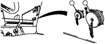
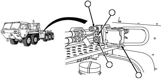
Figure 2-22. Power Interface Kit (If Equipped)
Key
Control or Indicator
Function
1
Power Interface Hydraulic
Quick Disconnect
Connection that supplies hydraulic fluid
pressure to an engineering mission module.
2
Power Interface Air
Quick Disconnect
Connection that supplies air pressure to
an engineering mission module.
3
Power Interface Electrical
Connector (5 pin)
Connection to auxillary equipment high
idle circuit of an engineering module.
4
Power Interface Electrical
Connector (23 pin)
Connection that supplies electrical power
to an engineering mission module.
3
4
2
1
4
3
|