|
| |
TM 9-2320-364-20-2
2-1223
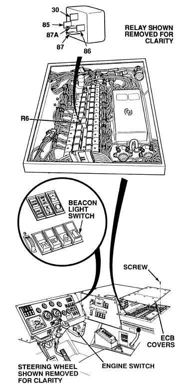
(1) Remove 15 screws and two
ECB covers.
(2) Pull beacon relay R6 out of socket
enough to access terminals with a test
probe.
(3) Set multimeter select switch to
volts dc.
(4) Connect positive (+) multimeter lead
to wire 1413 at beacon relay R6,
terminal 30.
(5) Connect negative (–) multimeter lead
to a known good ground.
(6) Turn ON ENGINE switch
(TM 9-2320-364-10).
(7) Turn on beacon light switch.
(a) If 10 to 14 vdc are not present,
repair wire 1413
(see schematic Fig 2-30).
(b) If 10 to 14 vdc are present,
wire 1413 is OK.
(8) Turn OFF ENGINE switch.
VOLTAGE TEST
Remove all jewelry such as rings, dog tags, bracelets, etc. If jewelry or tools contact positive electrical
circuits, a direct short may result. Damage to equipment, injury or death to personnel may occur.
Circuit breakers CB5, CB6, CB12, CB20, CB22, CB23 and relays R3, R13 - R19, R26, R28, R32, R33
are always electrically hot and can cause severe injury to personnel. Care must be exercised when
working under the electrical circuit board cover
(1) Connect positive (+) multimeter lead
to wire 1184 at beacon relay R6,
terminal 85.
(2) Connect negative (–) multimeter lead
to a known good ground.
(3) Turn ON ENGINE switch
(TM 9-2320-364-10).
(a) If 10 to 14 vdc are not present,
repair wire 1184
(see schematic Fig 2-30) or notify
DS Maintenance.
(b) If 10 to 14 vdc are present,
wire 1184 is OK.
(4) Turn OFF ENGINE switch.
VOLTAGE TEST
Relay tests must be performed with relay
partially removed.
NOTE
|