|
| |
TM 9-2320-364-20-2
1279
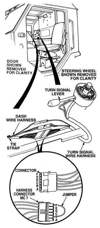
(1) Disconnect turn signal/flasher
connector MC7.
(2) Connect jumperwire between
terminals B and F of connector MC7.
(a) If right rear turn signal does not
operate, repair wire 1004 (see
schematic Fig 2-32) or notify DS
Maintenance. Verify repair, go to
Step 6 of this Fault.
(b) If right turn signal operates,
replace turn signal/flasher
switch (Para 7-35).
(3) Remove jumperwire.
(4) Connect turn signal/flasher connector
to harness connector MC7.
VISUAL INSPECTION
10 to 14 vdc are always present at terminals E and F of connector MC7.
Remove all jewelry such as rings, dog tags, bracelets, etc. If jewelry or tools contact positive electrical
circuits, a direct short may result. Damage to equipment, injury or death to personnel may occur.
|