|
| |
TM 9-2320-364-20-2
2-1349
Remove all jewelry such as rings, dog tags, bracelets, etc. If jewelry or tools contact positive electrical
circuits, a direct short may result. Damage to equipment, injury or death to personnel may occur.
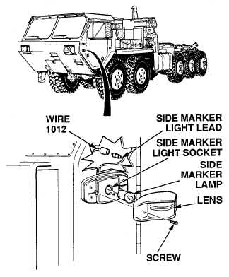
(1) Disconnect wire 1012 from side
marker light.
(2) Set multimeter select switch to
volts dc.
(3) Connect positive (+) multimeter lead
to wire 1012.
(4) Connect negative (–) multimeter lead
to a known good ground.
(5) Turn ON ENGINE switch
(TM 9-2320-364-10).
(a) If 10 to 14 vdc are not present,
turn OFF ENGINE switch and
repair wire 1012 (see schematic
Fig 2-34) or notify DS
Maintenance.
(b) If 10 to 14 vdc are present, wire
1012 is OK.
(6) Turn OFF ENGINE switch.
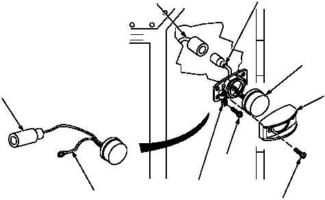
(7) Connect wire 1012 to side
marker light or LED.
VOLTAGE TEST
If working on side marker LED,
go to Step (2).
NOTE
WIRE
1012
SIDE MARKER
LIGHT LEAD
SIDE
MARKER
LED
LENS
SCREW
SCREW
WHITE GROUND
WIRE
WHITE GROUND
WIRE
SIDE MARKER
LIGHT LEAD
|