|
| |
TM 9-2320-364-20-2
2-1387
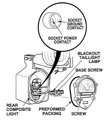
(1) Loosen six screws and remove
composite light cover and preformed
packing. Discard preformed packing.
(2) Push in and rotate blackout taillight
base screw counter-clockwise and
remove taillight lamp.
(3) Set multimeter select switch to
volts dc.
(4) Connect positive (+) multimeter lead
to socket power contact of blackout
taillight socket.
(5) Connect negative (–) multimeter lead
to a known good ground.
(6) Turn ON ENGINE switch
(TM 9-2320-364-10).
(a) If 10 to 14 vdc are not present,
turn OFF ENGINE switch and go
to Step 8 of this Fault.
(b) If 10 to 14 vdc are present,
turn OFF ENGINE switch and go
to Step 7 of this Fault.
VOLTAGE TEST
Remove all jewelry such as rings, dog tags, bracelets, etc. If jewelry or tools contact positive electrical
circuits, a direct short may result. Damage to equipment, injury or death to personnel may occur.
(1) Set multimeter select switch to ohms.
(2) Is there continuity between blackout
taillight socket ground contact and a
known good ground?
(a) If there is no continuity,
replace rear composite light
(Para 7-47).
(b) If there is continuity, replace
blackout taillight lamp
(Para 7-51).
CONTINUITY TEST
|