|
| |
TM 9-2320-364-20-2
2-1401
Remove all jewelry such as rings, dog tags, bracelets, etc. If jewelry or tools contact positive electrical
circuits, a direct short may result. Damage to equipment, injury or death to personnel may occur.
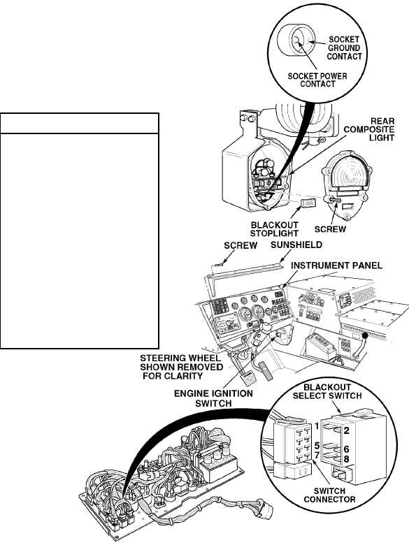
(1) Remove ten screws and sunshield
from instrument panel.
(2) Pull top of instrument panel towards
steering wheel.
(3) Remove BLACKOUT MARKER
lights switch.
(4) Set multimeter select switch to
volts dc.
(5) Connect positive (+) multimeter lead
to blackout marker switch
connector, terminal 5.
(6) Connect negative (–) multimeter
lead to a known good ground.
(7) Turn ON ENGINE switch
(TM 9-2320-364-10).
(8) Turn on BLACKOUT LIGHTS
selector switch.
(a) If 10 to 14 vdc are not present,
turn OFF ENGINE switch and
repair wire 1674 (see
schematic Fig 2-35) or notify
DS Maintenance.
(b) If 10 to 14 vdc are present,
turn OFF ENGINE switch and
go to Step 2 of this Fault.
VOLTAGE TEST
|