|
| |
TM 9-2320-364-20-2
2-855
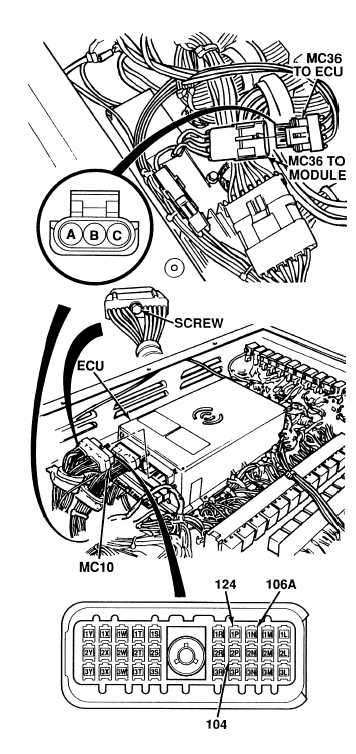
(1) Disconnect connector MC36.
(2) Loosen screw and disconnect
connector MC10 from ATEC ECU.
(3) Set multimeter select switch to ohms.
(4) Is there continuity on wire 104
between connector MC36, terminal B
and connector MC10, terminal 2P?
(a) If there is no continuity, repair wire
(see schematic Fig 2-22) or notify
DS Maintenance.
(b) If there is continuity, wire 104
is OK.
(5) Repeat Step (4) above for wire 124 at
connector MC36, terminal A and
connector MC10, terminal 1P. Go to
Step (6) below.
(6) Repeat Step (4) above for wire 106A
at connector MC36, terminal C and
connector MC10, terminal 1N.
(7) Connect connector MC10 to ATEC
ECU and tighten screw.
(8) Connect connector MC36.
CONTINUITY TEST
Remove all jewelry such as rings, dog tags,
bracelets, etc. If jewelry or tools contact
positive electrical circuits, a direct short
may result. Damage to equipment, injury or
death to personnel may occur.
Voltage is always present at circuit breakers
CB5, CB6, CB12, CB20, CB22, CB23 and relays
R3, R13 - R19, R26, R28, R32, R33 and can
cause severe injury to personnel. Non-metallic
tools shall be used when removing relays.
|