|
| |
TM 9-2320-364-20-2
2-857
(1) Set multimeter select switch to
volts dc.
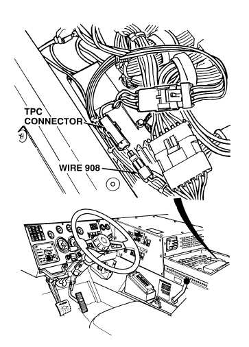
(2) Disconnect TPC module connector.
(3) Connect positive (+) multimeter lead
to TPC module connector wire 908.
(4) Connect negative (–) multimeter lead
to a known good ground.
(5) Turn ON ENGINE switch
(TM 9-2320-364-10).
(a) If 9.0 to 10.5 vdc are not present,
perform Steps (6) and (7) below
and replace DDEC II ECM
(Para 7-56) or DDEC III ECM
(Para 7-57).
(b) If 9.0 to 10.5 vdc are present,
DDEC ECM is OK.
(6) Turn OFF ENGINE switch.
(7) Connect TPC connector.
VOLTAGE TEST
Remove all jewelry such as rings, dog tags, bracelets, etc. If jewelry or tools contact positive electrical
circuits, a direct short may result. Damage to equipment, injury or death to personnel may occur.
Voltage is always present at circuit breakers CB5, CB6, CB12, CB20, CB22, CB23 and relays R3,
R13 - R19, R26, R28, R32, R33 and can cause severe injury to personnel. Non-metallic tools shall be
used when removing relays.
|