|
| |
TM 9-2320-364-20-2
2-1639
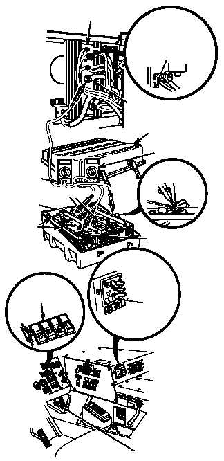
NEG (–)
TERMINAL
MULTIMETER
TWO
MULTIMETER
ONE
BATTERY
BOX COVER
TERMINAL A
DUVAC
CONTROLLER
POS. (+)
TERMINAL
”A” GROUP
”B” GROUP
NEG. (–)
TERMINAL
FAN
CONTROL
SWITCH
ENGINE
SWITCH
POTENTIOMETER
ADJUSTING
SCREW
HEADLIGHT
SWITCH
(1) Remove battery box cover.
(TM 9-2320-364-10).
(2) Connect multimeter one positive (+)
lead to positive (+) terminal on
“B” batteries and multimeter one
negative (–) lead to negative (–)
terminal on group “B” batteries.
(3) Connect multimeter two positive (+)
lead to terminal A of DUVAC
controller and multimeter two negative
lead to negative (–) terminal of group
“A” batteries.
(4) Start engine and turn on headlights and
heater.(TM 9-2320-364-10).
(5) Attempt to adjust DUVAC controller
until multimeter one reads 14.3-14.6
vdc.
(a) If 14.3-14.6 vdc cannot be
obtained, turn off heater, headlights
and engine switch and replace
DUVAC controller (Para 7-9).
(b) If 14.3-14.6 vdc can be obtained,
fault corrected. Turn off heater,
headlights and engine switch.
VOLTAGE TEST
Remove all jewelry such as rings, dog tags, bracelets, etc. If jewelry or tools contact positive electrical
circuits, a direct short may result. Damage to equipment, injury or death to personnel may occur.
Use caution when turning adjusting screw of potentiometer. Turning adjusting screw with too much force
may damage potentiometer.
DUVAC controller resets to the 24 vdc
charge mode approximately every 55
seconds. Make sure multimeter reads
26-30 vdc indicating the system is in the
24 vdc charge mode while reading on
multimeter one is taken.
Charging voltage is adjusted by turning
adjusting screw on potentiometer on
DUVAC controller. Turning to the right
increases voltage. Turning to the left
decreases voltage.
NOTE
|