|
| |
TM 9-2320-364-20-2
2-1667
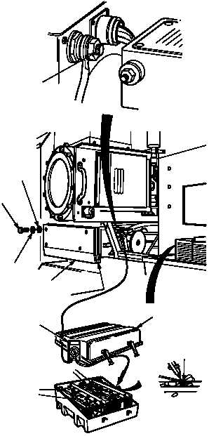
(1) Remove battery box cover
(TM 9-2320-364-10).
(2) Remove four screws, lockwashers,
washers, rubber and left front
side noise panel. Discard
lockwashers.
(3) Set multimeter select switch to
volts dc on multimeter.
(4) Connect multimeter positive (+)
lead to 12 volt terminal of alternator
and multimeter negative (–) lead
to negative (–) terminal of group
“A” batteries.
(5) Start engine and turn on headlights
and heater.
(6) Observe voltage indicated on
multimeter.
(a) If 13.8 - 14.2 vdc are not present,
replace voltage regulator
(Para 7-8).
(b) If 13.8 - 14.2 vdc are present,
voltage regulator is OK.
(7) Turn off heater, headlights and engine.
VOLTAGE TEST
Remove all jewelry such as rings, dog tags, bracelets, etc. If jewelry or tools contact positive electrical
circuits, a direct short may result. Damage to equipment, injury or death to personnel may occur.
Alternator is capable of producing over 40 vdc. Be careful when taking a voltage reading not to get shocked.
12 VOLT
TERMINAL
WASHER
SCREW
LOCKWASHER
RUBBER
PANEL
BATTERY
BOX COVER
MULTIMETER
NEG (–)
TERMINAL
“A” GROUP
B” GROUP
|