|
| |
TM 9-2320-364-20-3
2-2925
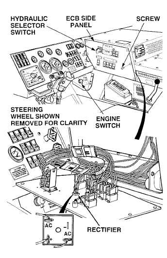
(1) Remove six screws and ECB side
panel.
(2) Tag, mark and disconnect three wires
from rectifier.
(3) Set multimeter to diode check.
(4) Connect positive (+) multimeter lead
to negative (–) rectifier terminal.
(5) Connect negative (–) multimeter lead
to each rectifier AC terminal one at
a time.
(a) If any VDC are not present at
either AC terminal, replace
rectifier.
(b) If any VDC are present at both AC
terminals, go to Step (6) below.
(6) Connect negative (–) multimeter lead
to positive (+) rectifier terminal.
(7) Connect positive (+) multimeter lead
to each rectifier AC terminal one at a
time.
(a) If any VDC are not present at
either AC terminal, replace
rectifier (Para 17-20).
(b) If any VDC are present at both AC
terminals, rectifier is OK.
(8) Connect three wires to rectifier.
(9) Install ECB side panel with six screws.
DIODE TEST
Remove all jewelry such as rings, dog tags, bracelets, etc. If jewelry or tools contact positive electrical
circuits, a direct short may result. Damage to equipment, injury or death to personnel may occur.
|