|
| |
TM 9-2320-364-20-3
2-2031
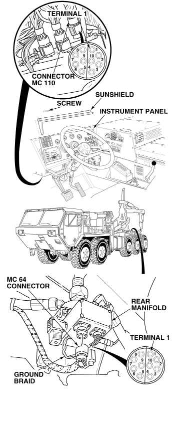
(1) Disconnect connector MC64 from
CTIS rear manifold.
(2) Set multimeter select switch to
ohms.
(3) Connect jumperwire between
wire 1072 on CTIS controller
connector MC110, terminal 1 and a
known good ground.
(4) Is there continuity between
connector MC64, terminal 1 and
rear manifold ground braid?
(a) If there is no continuity, repair
wire 1072 (see schematic
Fig 2-48) or notify DS
Maintenance, and perform
Steps (6) through (9) below.
(b) If there is continuity, wire 1072
is OK.
(5) Check continuity on remaining
wires in harness. The wires and
corresponding terminals are listed
below (see schematic Fig 2-48).
1073(2) 1070(6) 1068(9)
1076(3) 1066(7) 1074(10)
1071(4) Shield(8)
1067(5) to ground (MC 64 only)
(6) Remove jumperwire.
(7) Connect connector MC110 on back
of CTIS controller.
(8) Connect connector MC64 on CTIS
rear manifold.
(9) Install instrument panel and sun-
shield with ten screws.
CONTINUITY TEST
NOTE
Terminal (5) at MC 110 is plugged and does
not connect to terminal (5) on MC 64.
|