|
| |
TM 9-2320-364-20-3
2-2079
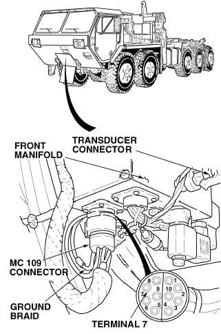
(1) Connect positive (+) multimeter lead
(with long probe installed) on terminal
7 at front manifold wire harness.
(2) Connect negative (–) multimeter
lead to a known good ground.
(3) Turn ON ENGINE switch.
(4) As assistant pushes CTIS START
button.
(a) If there is no voltage present, re-
place front manifold (Para 13-8).
(b) If there is voltage, Fault is not
corrected. Notify Supervisor.
(5) Turn OFF ENGINE switch.
(6) Close front access cover
(TM 9-2320-364-10).
VOLTAGE TEST
Remove all jewelry such as rings, dog tags, bracelets, etc. If jewelry or tools contact positive electrical circuits,
a direct short may result. Damage to equipment, injury or death to personnel may occur.
NOTE
All connectors must be fully plugged in to
perform this test.
|