|
| |
TM 9-2320-364-20-3
2-2109
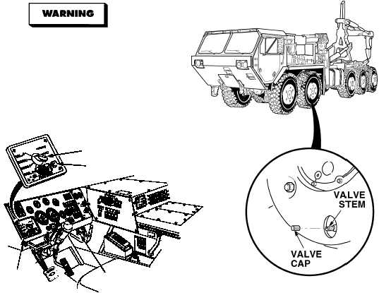
ENGINE
SWITCH
SELECTOR
START
BUTTON
STEERING
SHOWN
FOR
CTIS
CONTROLLER
(1) Remove valve cap from any wheel valve
stem on Axles No. 3 through No. 5.
(2) Using tire gage, deflate any one tire on
Axles No. 3 through No. 5 to 40 psi
(276 kPa).
(3) Start engine (TM 9-2320-364-10).
(4) Set CTIS controller selector to
HIGHWAY.
(5) Press CTIS START button.
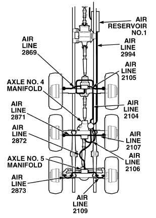
(6) Check CTIS air line 2994 for
damage, crimps or leaks (see
schematic Fig 2-49).
(a) If air line 2994 is damaged, crimped
or leaking; perform Steps (7) and (8)
below, and tighten fittings, replace
air line (see Para 12-36 and
schematic Fig 2-49).
(b) If there are no leaks, crimps or
damage; air line 2994 and fittings
are OK.
(7) Turn OFF ENGINE switch.
(8) Install valve cap on wheel valve stem.
VISUAL INSPECTION
Wear safety goggles when performing
leakage tests on valves. Failure to do so
may result in serious eye injury due to
high pressure air.
Exercise extreme caution when working
around wheels or under truck while engine
is operating. Movement of truck may cause
injury or death to personnel.
NOTE
Soap and water solution can be used to
visually check for leaks.
|