|
| |
TM 9-2320-364-20-3
2-2305
(1) Remove LHS control assy
(Para 7-40).
(2) Remove four screws, lockwashers and
LHS control box cover. Discard
lockwashers.
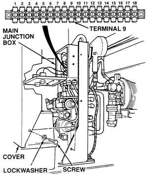
(3) Loosen four screws and open main
junction box.
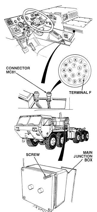
(4) Connect main junction box terminal 9
to a known good ground using jumperwire.
(5) Set multimeter select switch to ohms.
(6) Is there continuity between harness
connector MC81, terminal F and a
known good ground?
(a) If there is no continuity, repair wire
1472 (see schematic Fig 2-52) or
notify DS Maintenance.
(b) If there is continuity, replace LHS
control assy (Para 7-40) and
perform Steps (7) and (8) below.
(7) Remove jumperwire from main
junction box terminal F and ground.
(8) Install LHS control assy
(Para 7-40).
CONTINUITY TEST
Remove all jewelry such as rings, dog tags, bracelets, etc. If jewelry or tools contact positive electrical
circuits, a direct short may result. Damage to equipment, injury or death to personnel may occur.
When opening the main junction box, do not pull or allow front of junction box to hang by the wire connections.
Failure to comply will damage the wire connections.
NOTE
Only remove center screw on engine side of LHS control box cover.
|