|
| |
TM 9-2320-364-20-3
2-2317
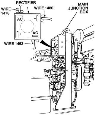
(1) Disconnect all wires from rectifier.
(2) Set multimeter select switch
to diode position.
(3) Connect positive (+) multimeter lead
at negative terminal.
(4) Connect negative (–) multimeter lead
at each AC terminal.
(a) If there are not any vdc
present at both AC terminals,
replace rectifier (Para 7-19).
(b) If there is any vdc present at both
AC terminals, perform Steps (5)
and (6) below.
(5) Connect negative (–) multimeter lead
at positive terminal on rectifier.
(6) Connect positive (+) multimeter lead
at each AC terminal.
(a) If there is not any vdc
present at both AC terminals,
replace rectifier (Para 7-19) and
perform Step (7) below.
(b) If there is any vdc present, rectifier
is OK.
(7) Connect wires to rectifier.
RECTIFIER TEST
Remove all jewelry such as rings, dog tags, bracelets, etc. If jewelry or tools contact positive electrical
circuits, a direct short may result. Damage to equipment, injury or death to personnel may occur.
Do not allow the LHS control box assembly cover to hang from console by the wire connections to the
control box assembly. Failure to comply will damage the wire connections.
NOTE
Tag and mark all wires prior to disconnecting.
|