|
| |
TM 9-2320-364-20-3
2-2447
(1) Remove four screws, lockwashers and
LHS control box cover. Discard
lockwashers.
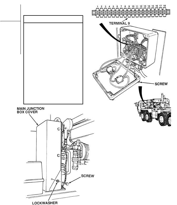
(2) Loosen four screws and open main
junction box.
(3) Set multimeter selector switch
to volts dc.
(4) Connect positive (+) multimeter lead
to main junction box, terminal 9.
(5) Connect negative (–) multimeter lead
to a known good ground.
(6) Turn ON ENGINE switch
(TM 9-2320-364-10).
(a) If there are not 22 to 28 vdc
present, perform Steps (7)
and (8) below and go to
Fault 4 of this chapter.
(b) If there are 22 to 28 vdc present,
perform Steps (7) through (9)
below.
(7) Turn OFF ENGINE switch.
(8) Close main junction box and tighten
four screws.
(9) Install LHS control box cover, four
lockwashers and screws.
VOLTAGE TEST
Remove all jewelry such as rings, dog tags, bracelets, etc. If jewelry or tools contact positive electrical
circuits, a direct short may result. Damage to equipment, injury or death to personnel may occur.
NOTE
Only remove center screw on engine side of LHS
control box cover.
|