|
| |
TM 9-2320-364-20-3
2-1935
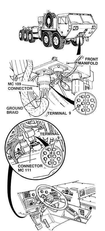
(1) Insert positive (+) multimeter lead,
with long probe installed, at back of
connector MC109, terminal 9.
(2) Connect negative (–) multimeter lead
to front manifold ground braid.
(3) Turn ON ENGINE switch
(TM 9-2320-364-10).
(a) If 13-14 vdc are not present,
turn OFF ENGINE switch and
replace front manifold (Para 13-8).
(b) If 13-14 vdc are present, front
manifold is OK.
(4) Turn OFF ENGINE switch.
VOLTAGE TEST
Remove all jewelry such as rings, dog tags,
circuits, a direct short may result. Damage to
(1) Disconnect harness connectors
MC109 and MC111.
(2) Set multimeter select switch to ohms.
(3) Is there continuity between harness
connectors MC109, terminal 9 and
MC111, terminal 9?
(a) If there is no continuity, repair
wire 1064 (see schematic
Fig 2-48) or notify DS
Maintenance.
(b) If there is continuity, wire 1064 is
OK, replace CTIS controller
(Para 13-7).
(4) Connect harness connectors MC109
and MC111.
(5) Close front access cover
(TM 9-2320-364-10).
CONTINUITY TEST
|