|
| |
TM 9-2320-364-20-3
2-2475
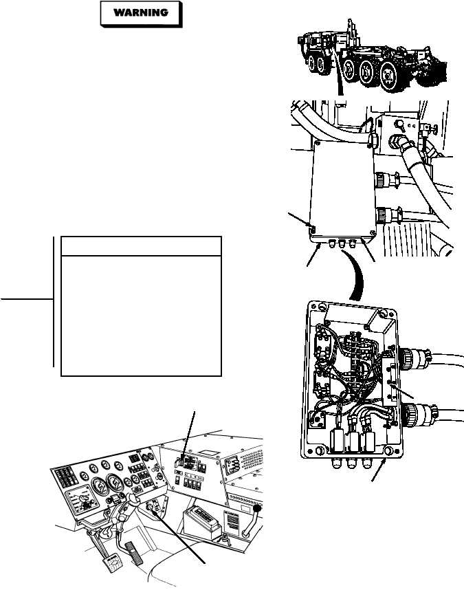
(1) Loosen four screws and remove
powerbox cover (Para 21-16).
(2) Turn ON engine switch
(TM 9-2320-364-10).
(3) Set hydraulic selector switch to
AUTO or MAN mode.
(4) Observe LED #2 lamp in powerbox.
(a) If lamp is not ON, perform STEP (5)
below and go to Step 6 of this Fault.
(b) If LED #2 lamp is on and LHS is
inoperative, perform Step (5) below
and go to Step 2 of this Fault.
(5) Turn OFF engine switch.
VISUAL INSPECTION
Remove all jewelry such as rings, dog tags,
bracelets, etc. If jewelry or tools contact positive
electrical circuits, a direct short may result.
Damage to equipment, injury or death to
personnel may occur.
STEERING WHEEL
SHOWN REMOVED
FOR CLARITY
ENGINE SWITCH
HYDRAULIC
SELECTOR
SWITCH
POWERBOX
SCREWS
COVER
LED #2 LAM
POWERBOX
|