|
| |
TM 9-2320-364-20-3
2-2523
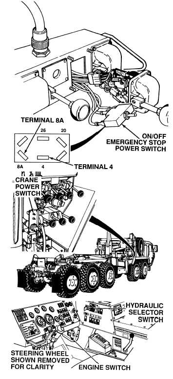
(1) Remove Boom controller and ON/OFF
EMERGENCY STOP switch from
remote control unit, but do not
disconnect wires (Para 18-4).
(2) Set multimeter select switch to volts.
(3) Connect positive (+) multimeter lead
to terminal 4 on ON/OFF
EMERGENCY STOP switch.
(4) Connect negative (–) multimeter lead
to a known good ground.
(5) Turn ON ENGINE switch
(TM 9-2320-364-10).
(6) Put hydraulic selector switch in
CRANE/SRW position.
(7) Turn ON crane POWER switch.
(a) If 22 to 28 vdc are not present,
perform Step (8) below and repair
wire 4 from remote control
unit hookup terminal H to
ON/OFF EMERGENCY STOP
switch (see schematic Fig 2-58) or
notify DS Maintenance.
(b) If 22 -28 vdc are present, perform
Step (8) below and go to Step 5
of this Fault.
(8) Put following switches in OFF
position: crane POWER switch,
hydraulic selector switch and ENGINE
switch.
VOLTAGE TEST
Remove all jewelry such as rings, dog tags, bracelets etc. If jewelry or tools contact positive electrical
circuits, a direct short may result. Damage to equipment, injury or death to personnel may occur.
(1) Connect positive (+) multimeter lead
to terminal 8A where connected to
ON/OFF EMERGENCY STOP switch.
(2) Connect negative (–) multimeter lead
to a known good ground.
(3) Turn ON ENGINE switch
(TM 9-2320-364-10).
(4) Put hydraulic selector switch in
CRANE/SRW position.
(5) Turn ON crane POWER switch.
(6) Turn ON remote control unit ON/OFF
EMERGENCY STOP switch.
(a) If 22 to 28 vdc are not present,
perform Step (7) below and
replace switch (Para 18-4).
(b) If 22 to 28 vdc are present,
perform Step (7) below and go to
Step 6 of this Fault.
(7) Put following switches in OFF
position: crane POWER switch,
hydraulic selector switch and ENGINE
switch.
VOLTAGE TEST
|