|
| |
TM 9-2320-364-20-3
2-1965
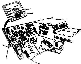
ENGINE
SWITCH
SELECTOR
START
BUTTON
STEERING WHEEL
SHOWN REMOVED
FOR CLARITY
CTIS
CONTROLLER
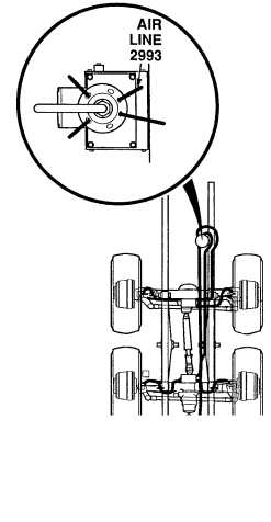
(1) Remove valve cap from any
valve stem on Axles No. 1 or No. 2.
(2) Using tire gage, deflate any one tire
on Axles No. 1 or No. 2 to 40 psi
(276 kPa).
(3) Start engine (TM 9-2320-364-10).
(4) Set CTIS controller selector to
HIGHWAY.
(5) Press CTIS START button.
(6) Check CTIS air line No. 2993 and fittings
for damage, crimps, or leaks (see
schematic Fig. 2-49).
(a) If air line No. 2993 or fittings are
damaged, crimped or leaking,
perform Steps (7) and (8) below,
and tighten fittings, replace air
lines (Para 12-36 and schematic
Fig 2-49).
(b) If there are no leaks, crimps or
damage, air line and fittings are
OK.
(7) Turn OFF ENGINE switch.
(8) Install valve cap on valve stem.
VISUAL/AUDIBLE INSPECTION
Wear safety goggles when performing leakage tests on valves. Failure to do so may result in serious
eye injury due to high pressure air.
Exercise extreme caution when working around wheels or under truck while engine is operating.
Movement of truck may cause injury or death to personnel.
NOTE
Excessive inflation times without a low air light are caused by minor leaks in CTIS system.
CTIS air lines are pressurized only when CTIS is in inflate, deflate or test cycles.
Excessive inflation times, sometimes accompanied by low air light is normal if engine is at idle speed and/or air
operated accessories are being used.
CTIS initially and periodically checks for system air leaks. CTIS controller will display a flashing LOW AIR light
and will shut off if about 6 psi (41 kPa) cannot be maintained by the CTIS system. The manifold will click during
this check.
|