|
| |
TM 9-2320-364-20-3
2-2819
(1) Start engine (TM 9-2320-364-10).
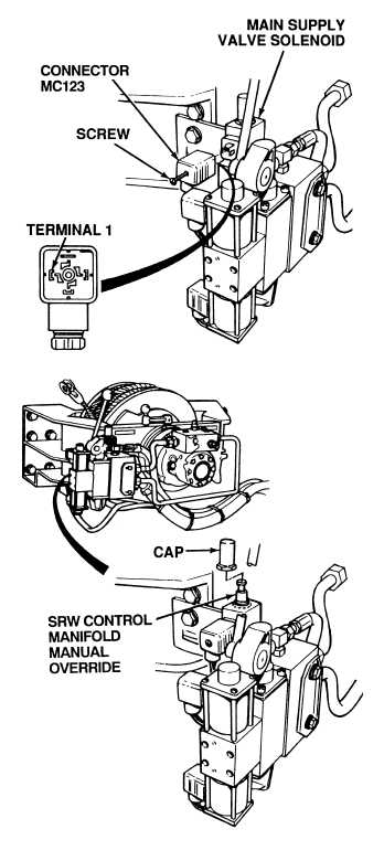
(2) Remove cap from SRW control
manifold manual override.
(3) Rotate manual override button
and pull up.
(4) Operate SRW.
(a) If SRW does not operate, SRW
control manifold is faulty. Perform
Steps (5) through (7) below and
notify DS Maintenance.
(b) If SRW does operate, perform
Steps (5) through (7) below and
go to Step 3 of this Fault.
(5) Push down on manual override button
and rotate to lock in down position.
(6) Install cap on manual override and
tighten securely.
(7) Turn OFF ENGINE switch.
MANUAL OVERRIDE TEST
Remove all jewelry such as rings, dog tags, bracelets etc. If jewelry or tools contact positive electrical
circuits, a direct short may result. Damage to equipment, injury or death to personnel may occur.
Adhesives, solvents, and sealing compounds
can burn easily, can give off harmful
vapors, and are harmful to skin and clothing.
To avoid injury or death, keep away from open
fire and use in a well-ventilated area. If
adhesive, solvent, or sealing compound gets
on skin or clothing, wash immediately with
soap and water.
(1) Loosen screw and disconnect
solenoid connector MC123 from SRW
control manifold main supply valve.
(2) Connect positive (+) multimeter lead
to wire 1732 at main supply valve
solenoid connector MC123,
terminal 1.
(3) Connect negative (–) multimeter lead
to a known good ground.
(4) Turn ON ENGINE switch
(TM 9-2320-364-10).
(5) Set hydraulic selector switch to
CRANE/SRW position.
(a) If 22 to 28 vdc are not present,
perform Steps (6) through (9)
below and go to Step 4 of this
Fault.
(b) If 22 to 28 vdc are present, wire
1732 is OK. Perform Steps (6)
and (7) below and go to Step 5
of this Fault.
(6) Set hydraulic selector switch to OFF
position.
(7) Turn OFF ENGINE switch.
(8) Install connector on SRW control.
(9) Tighten connector screw and coat
head of connector screw with
adhesive.
VOLTAGE TEST
|