|
| |
TM 9-2320-364-20-4
12-154
12-33. LOAD SENSING VALVE REPLACEMENT (CONT).
(12)
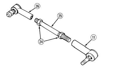
Loosen two locknuts (24) on metric
rod (25).
(13)
Remove lower head link (11), upper head
link (26) and two locknuts (24) from metric
rod (25).
b.
Installation.
(1)
Position two locknuts (24), upper head
link (26) and lower head link (11) on metric
rod (25).
Adhesives, solvents, and sealing compounds can burn easily, can give off harmful vapors, and
are harmful to skin and clothing. To avoid injury or death, keep away from open fire and use
in well-ventilated area. If adhesive, solvent, or sealing compound gets on skin or clothing,
wash immediately with soap and water.
NOTE
Perform Steps (2) and (3) if left side load sensing valve was removed.
Perform Steps (4) and (5) if right side load sensing valve was removed.
Install elbows and tees in positions noted prior to removal.
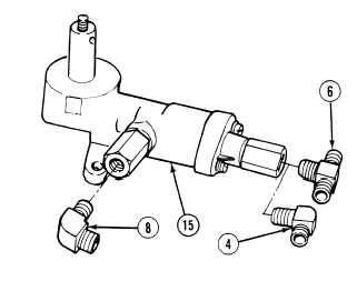
(2)
Apply sealing compound to threads of
elbows (4) and (8).
(3)
Install elbows (4) and (8) on load sensing
valve (19).
(4)
Apply sealing compound to threads of
elbow (8) and tee (6).
(5)
Install elbow (8) and tee (6) on load sensing
valve (15).
|