|
| |
TM 9-2320-364-20-4
12-155
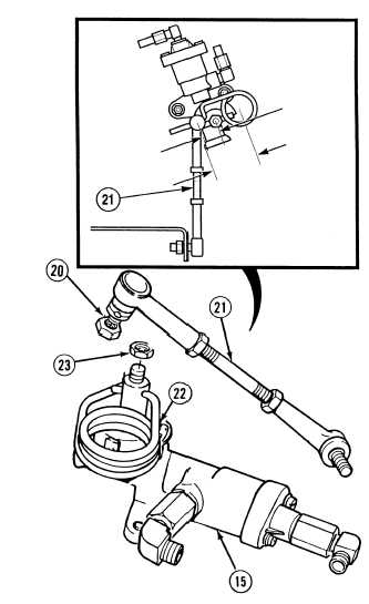
NOTE
Threads of link assembly
must be threaded 1.57
0.06 in. (39.88 1.52 mm)
in both the upper and lower
head link.
When installing upper head
link, ensure distance is 1 in.
(25.4 mm) between center of
upper head link and center of
control spring jam nut.
(6)
Install link assembly (21) and control spring
(22) on load sensing valve (15) with jam nuts
(20) and (23). Tighten jam nuts (20) and
(23).
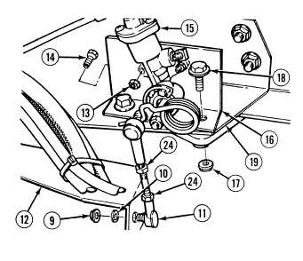
(7)
Install load sensing valve bracket (16) on
frame (19) with two screws (18) and
locknuts (17).
(8)
Install load sensing valve (15) on load
sensing valve bracket (16) with two
screws (14) and locknuts (13).
(9)
Install lower head link (11), lockwasher (10)
and nut (9) on axle bracket (12).
(10)
Tighten two jam nuts (24) on link
assembly (21).
1.00 IN.
(25.4 MM)
2.50 IN.
(63.5 MM)
|