|
| |
TM 9-2320-364-20-4
2-3103
2
1
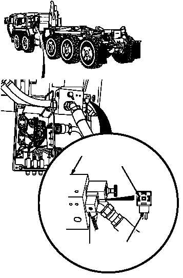
(1) Disconnect connector MC134 from
auxiliary supply valve.
(2) Connect positive (+) multimeter lead
to connector MC134 terminal 1.
(3) Connect negative (–) multimeter lead to
a known good ground.
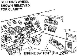
(4) Turn ON ENGINE switch
(TM 9-2320-364-10).
(a) If 22 to 28 vdc are not present,
perform Step (5) below and repair
wire 1792 (see schematic Fig
2-76) or notify DS Maintenance.
(b) If 22 to 28 vdc are present, perform
Step (5) below and go to
Step 20 of this Fault.
(5) Turn OFF ENGINE switch.
VOLTAGE TEST
Remove all jewelry such as rings, dog tags,
bracelets, etc. If jewelry or tools contact
positive electrical circuits, a direct short may
result. Damage to equipment, injury or death
to personnel may occur.
AUXILIARY
SUPPLY VALVE
CONNECTOR
MC134
CONNECTOR
MC134
TERMINAL 1
|