|
| |
TM 9-2320-364-20-4
7-83
d.
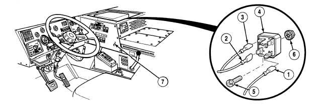
Electronic Control Box (ECB) Side Panel Rectifier Replacement.
(1)
Removal.
(a)
Remove wire 1744-1724 (1), wire 1733-1733 (2) and wire 1734 (3) from rectifier (4).
(b)
Remove screw (5), locknut (6) and rectifier (4) from ECB panel (7). Discard locknut.
(2)
Installation.
(a)
Install rectifier (4) on ECB panel (7) with screw (5) and locknut (6).
(b)
Install wire 1734 (3), wire 1733-1733 (2) and wire 1744-1724 (1) on rectifier (4).
e.
Follow-On Maintenance:
Install heater panel, (Para 17-4).
Install Electronic Control Box (ECB) cover, (Para 17-22).
Install instrument panel, (Para 7-13).
Connect batteries, (Para 7-87).
Remove wheel chocks, (TM 9-2320-364-10).
END OF TASK
|