|
| |
TM 9-2320-364-20-4
7-90
7-22. BATTERY GAGE REPLACEMENT (CONT).
(3)
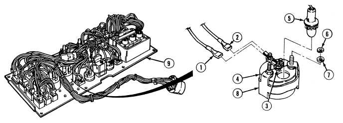
Remove two nuts (6) and lockwashers (7) from rear of battery gage mounting bracket (8).
(4)
Remove battery gage mounting bracket (8) from rear of battery gage (4).
(5)
Remove battery gage (4) from instrument panel (9).
b.
Installation.
NOTE
Both battery gages are installed the same way.
Positive wire is numbered 1276 for 12 volt gage.
Positive wire is numbered 1702 for 24 volt gage.
Ensure face of gage is aligned properly with dash during installation.
(1)
Install battery gage (4) in instrument panel (9).
(2)
Install battery gage mounting bracket (8) on rear of battery gage (4).
(3)
Install two lockwashers (7) and nuts (6) on rear of battery gage mounting bracket (8).
(4)
Install lamp socket 1052 (5) on rear of battery gage (4).
(5)
Install wire 1276 or 1702 (1) and wire 1435 (2) on terminals (3) on rear of battery gage (4).
c.
Follow-On Maintenance:
Install instrument panel, (Para 7-13).
Check operation, (TM 9-2320-364-10).
Remove wheel chocks, (TM 9-2320-364-10).
END OF TASK
|