|
| |
TM 9-2320-364-20-4
7-101
(2)
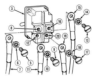
Remove screw (5), lockwasher (6) and wire
1939B (7) from terminal 2 (8) on toggle
switch (3).
(3)
Remove screw (9), lockwasher (10) and wire
1940B (11) from terminal 3 (12) on toggle
switch (3).
(4)
Remove screw (13), lockwasher (14) and
wire 1938B (15) from terminal 5 (16) on
toggle switch (3).
(5)
Remove screw (17), lockwasher (18) and
wire 1952B (19) from terminal 6 (20) on
toggle switch (3).
b.
Installation.
(1)
Intall wire 1952B (19), lockwasher (18) and
screw (17) on terminal 6 (20) of toggle
switch (3).
(2)
Install wire 1938B (15), lockwasher (14)
and screw (13) on terminal 5 (16) of toggle
switch (3).
(3)
Install wire 1940B (11), lockwasher (10)
and screw (9) on terminal 3 (12) of toggle
switch (3).
(4)
Install wire 1939B (7), lockwasher (6) and
screw (5) on terminal 2 (8) of toggle
switch (3).
(5)
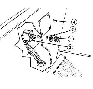
Install toggle switch (3), lockwasher (2) and
nut (1) on heater control panel (4).
c.
Follow-On Maintenance:
Install heater compartment cover, (Para 17-4).
Connect batteries, (Para 7-87).
Remove wheel chocks, (TM 9-2320-364-10).
END OF TASK
|