|
| |
TM 9-2320-364-20-4
7-130
7-39. PROXIMITY SWITCH REPLACEMENT/ADJUSTMENT (MAIN FRAME
DOWN) (CONT).
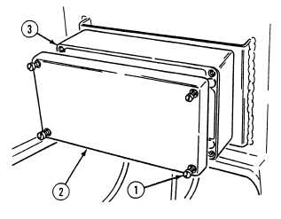
(6)
Position junction box cover (2) on junction
box (3) and tighten four screws (1).
c.
Adjustment.
NOTE
Proximity switch mounting plate
and middle frame have slotted
holes to aid in adjustment.
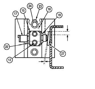
(1)
Adjust height between top of proximity
switch (17) and top of target plate (27).
Height should be 3/8 in. 3/32 in. (9.65 mm
.25 mm).
(2)
Tighten proximity switch mounting plate
(18) with two screws (24) and locknuts (23).
(3)
Adjust clearance between proximity switch
(17) and target plate (27). Clearance should
be .125 in. .01 in. (3.175 mm .25 mm).
(4)
Tighten two screws (13) on clamp halves (15).
d.
Follow-On Maintenance:
Connect batteries, (Para 7-87).
Check LHS operation, (TM 9-2320-364-10).
Remove wheel chocks, (TM 9-2320-364-10).
END OF TASK
3/8 IN.
3/32 IN.
(9.65 MM
.25 MM)
.125 IN.
.01 IN.
(3.175 MM
.25 MM)
|