|
| |
TM 9-2320-364-20-4
7-215
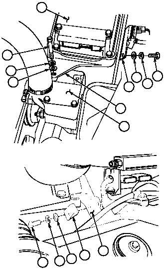
NOTE
Left injector wire harness should
be located under ECM bracket.
(7)
Position ECM (9) and ECM bracket (17) on
thermostat housing (47).
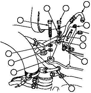
(8)
Position turbo boost sensor bracket (21) on
ECM bracket (17) with washer (20),
lockwasher (19) and screw (18). Do not
tighten screw.
(9)
Position washer (16), lockwasher (15) and
screw (14) on ECM bracket (17). Do not
tighten screw.
(10)
Position clip (34), washer (33), lockwasher
(32) and screw (31) on ECM bracket (17).
Do not tighten screw.
(11)
Position clip (30), washer (29), lockwasher
(28) and screw (27) on ECM bracket (17).
Do not tighten screw.
(12)
Position washer (26), lockwasher (25), and
screw (24) on ECM bracket (17). Do not
tighten screw.
Screws connecting bracket to
blower must be tightened first to
prevent damage to housing.
(13)
Tighten two screws (18) and (31) to
120-156 lb-in (14-18 Nm).
(14)
Tighten three screws (14), (27) and (24) to
17-20 lb-ft (23-27 Nm).
(15)
Install two fuel lines (22) on fittings (23).
17
34
33
32
31
17
14
15
16
18
20
19
21
24
28
25
17
27
29
30
26
47
9
22
23
23
22
|