|
| |
TM 9-2320-364-20-4
2-3013
Remove all jewelry such as rings, dog tags, bracelets, etc. If jewelry or tools contact positive electrical
circuits, a direct short may result. Damage to equipment, injury or death to personnel may occur.
Circuit breakers CB5, CB6, CB12, CB20,
CB22, CB23 and relays R3, R13 - R19, R26,
R28, R32 and R33 are always electrically
hot and can cause severe injury to
personnel. Care must be exercised when
working under the electrical circuit
board cover.
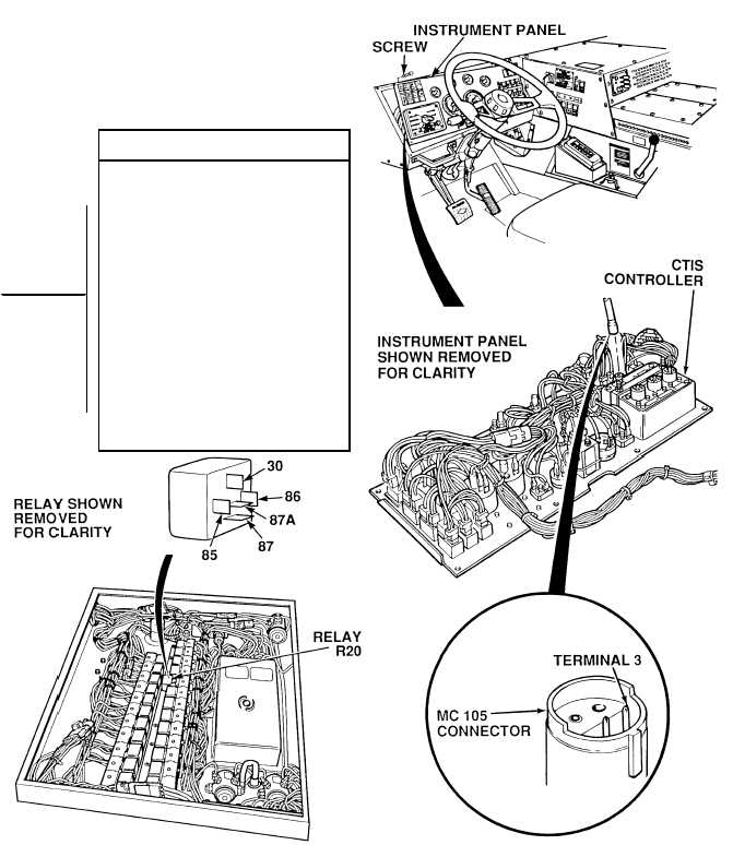
(1) Remove ten screws and
sunshield from instrument panel.
(2) Pull top of instrument panel
toward steering wheel.
(3) Disconnect CTIS controller connector
MC105.
(4) Set multimeter select switch to ohms.
(5) Is there continuity between CTIS
controller connector MC105,
terminal 3 and relay R20, terminal 85?
(a) If there is no continuity, repair
wire 1884 (see schematic Fig
2-72) or notify DS
Maintenance, and perform
Steps (6) and (7) below.
(b) If there is continuity, wire 1884
is OK.
(6) Connect CTIS controller connector
MC105 to CTIS controller.
(7) Install instrument panel and sunshield
with ten screws.
CONTINUITY TEST
NOTE
Relay test must be performed with relay
partially removed.
|