|
| |
TM 9-2320-364-20-4
7-371
(4)
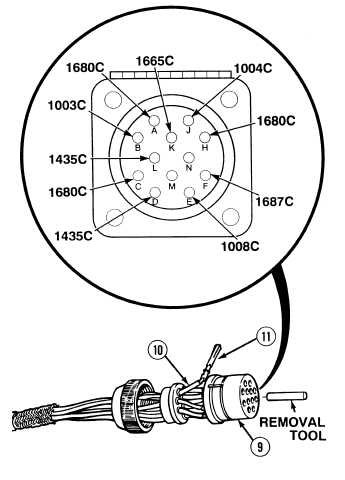
Using removal tool, remove wires (10) with
pins (11) from electrical connector
MC15 (9).
Table 7-6. 12-Pin Connector Wire Positions.
b.
Installation.
(1)
Install pins (11) and wires (10) in electrical
connector MC15 (9).
NOTE
Align tab with keyway.
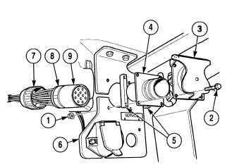
(2)
Install electrical connector MC15 (9) in
electrical connector housing (4).
(3)
Install collar boot (8) and collar (7) through
bracket (6) on electrical connector housing
(4).
NOTE
Electrical connector housing must
be positioned on mounting
bracket with keyway facing up.
(4)
Align four holes in electrical connector
housing (4) with holes in mounting
bracket (6).
(5)
Install two spacers (5), electrical connector
housing (4) and spring cover (3) on
mounting bracket (6) with four screws (2)
and locknuts (1).
c.
Follow-On Maintenance:
Connect batteries, (Para 7-87).
Remove wheel chocks, (TM 9-2320-364-10).
END OF TASK
Wire
Position
1680C
1003C
1680C
1435C
1008C
1687C
1680C
1004C
1665C
1435C
A
B
C
D
E
F
H
J
K
L
|