Order this information in Print

Order this information on CD-ROM

Download in PDF Format


Click here to make tpub.com your Home Page

Page Title: 12-2. BRAKE SHOE/SELF ADJUSTER REPAIR (CONT)
Back | Up | Next

Click here for a printable version

Google


Web
www.tpub.com

Home


Information Categories
.... Administration
Advancement
Aerographer
Automotive
Aviation
Combat
Construction
Diving
Draftsman
Engineering
Electronics
Food and Cooking
Math
Medical
Music
Nuclear Fundamentals
Photography
Religion
USMC
   
Products
  Educational CD-ROM's
Printed Manuals
Downloadable Books


TM 9-2320-364-20-4 12-4      12-2.  BRAKE SHOE/SELF ADJUSTER REPAIR (CONT). NOTE 
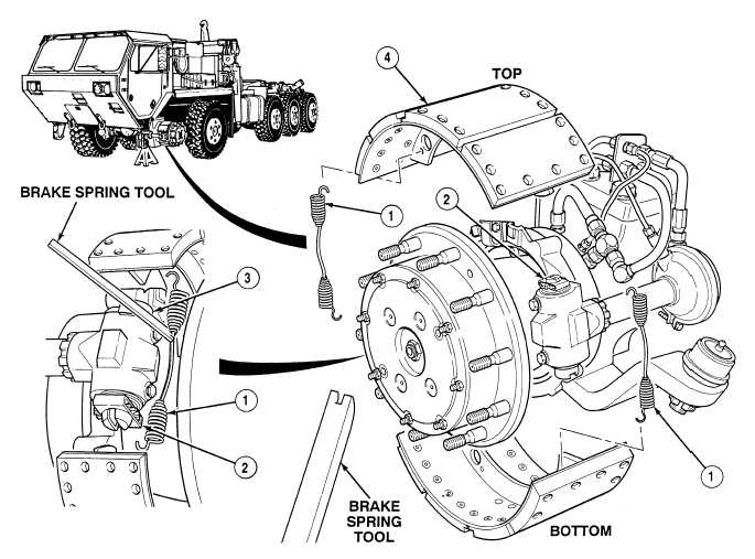
Note position and location of brake shoes prior to removal. All brake shoes are removed the same way.  Axle No. 1 left side shown. Axles No. 1 and 2 adjusting bolts are located on top rear and bottom front brake chambers. Axles No. 3 and 4 adjusting bolts are located on a single front brake chamber. Axle No. 5 adjusting bolts are located on a single rear brake chamber. (1) At rear return spring (1), position edge of brake spring tool against adjusting bolt (2) or brake spider assembly (3) and pry up to release upper end of rear return spring (1) from upper brake shoe (4).

Privacy Statement - Press Release - Copyright Information. - Contact Us - Support Integrated Publishing

Integrated Publishing, Inc. - A (SDVOSB) Service Disabled Veteran Owned Small Business