|
| |
TM 9-2320-364-20-4
12-8
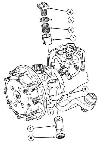
12-2. BRAKE SHOE/SELF ADJUSTER REPAIR (CONT).
d.
Assembly.
(1)
Install ring seal (8) on plunger assembly (9).
NOTE
Ensure slot on plunger assembly
lines up with guide assembly
pawl hole.
(2)
Install plunger assembly (9) into top right
side of brake spider (3).
NOTE
Ensure slot in adjusting plunger
lines up with guide assembly
pawl hole.
(3)
Install adjusting plunger (7) into lower right
side of brake spider (3).
(4)
Install ring seal (5) and actuator (6) on
adjusting bolt (7).
Adjusters may not function
properly if installed tightly
against the plunger.
(5)
Position adjusting bolt (4) in lower right side
of brake spider (3).
NOTE
Install guide assembly pawls in
location noted prior to removal.
(6)
Install two guide assembly pawls (1) and (2)
in right side of spider (3). Tighten guide
assembly pawls (1) and (2) to 22 lb-ft
(30 N.m).
(7)
Repeat Steps (1) through (6) for left side of
brake spider (3).
|