|
| |
TM 9-2320-364-20-5
15-31
(7)
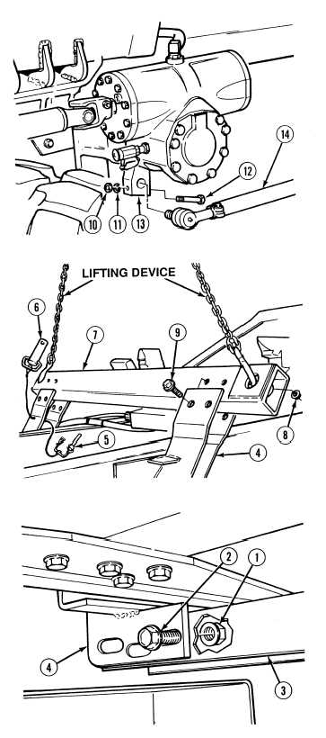
Install drag link (14) on steering arm (13)
with screw (12), lockwasher (11) and
nut (10).
Crossover tube weighs 100 lbs
(45 kg). Attach a suitable lifting
device prior to installation to
prevent possible injury to
personnel.
(8)
Attach lifting device to crossover tube (7).
(9)
Install crossover tube (7) in right and left
hard lift brackets (4) with eight screws (9)
and locknuts (8). Tighten locknuts to
375 lb-ft (508 N.m).
(10)
Install two pins (6) in crossover tube (7) with
two quick release pins (5).
Ensure larger radius cut-out on
crossmember is positioned
towards rear of truck or damage
to equipment may result.
(11)
Install crossmember (3) between right and
left hard lift brackets (4) with twelve
screws (2) and locknuts (1). Tighten
locknuts to 375 lb-ft (508 N.m).
c.
Follow-On Maintenance:
Install load sensing valves, (Para 12-33).
Install rear hard lift assembly, (Para 15-8).
Remove wheel chocks, (TM 9-2320-364-10).
END OF TASK
|