|
| |
TM 9-2320-364-20-5
15-47
Materials/Parts
Sealing Compound (Item 77, Appendix C)
Locknut (6) (Item 93, Appendix F)
This task covers:
a. Removal
b. Installation
c. Follow-On Maintenance
INITIAL SETUP
Personnel Required
Two
Equipment Condition
Engine OFF, (TM 9-2320-364-10)
Wheels chocked, (TM 9-2320-364-10)
Tools and Special Tools
Tool Kit, General Mechanic’s: Automotive
(Item 74, Appendix G)
Multiplier, Torque (Item 45, Appendix G)
Socket Set, 3/4 in. (Item 61, Appendix G)
Wrench, Combination 1-1/8
(Item 79, Appendix G)
Lifting Device, Minimum Capacity 375 lbs
(170 kg)
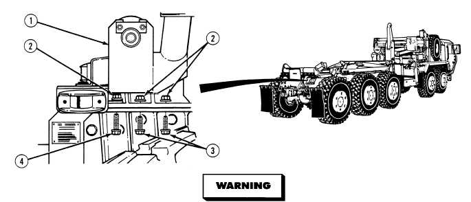
15-17. REAR ROLLER ASSEMBLY REPLACEMENT.
a.
Removal.
Rear roller assembly weighs 375 lbs (170 kg). Attach suitable lifting device prior to removal
or installation to prevent possible injury to personnel.
(1)
Attach lifting device to rear roller assembly (1).
(2)
Remove six locknuts (2), four screws (3) and two screws (4) from rear roller assembly (1). Discard
locknuts.
|