|
| |
TM 9-2320-364-20-5
20-58
Materials/Parts
Lockwasher (4) (Item 195, Appendix F)
This task covers:
a. Removal
b. Installation
c. Follow-On Maintenance
INITIAL SETUP
Equipment Condition
Engine OFF, (TM 9-2320-364-10)
Wheels chocked, (TM 9-2320-364-10)
Tools and Special Tools
Tool Kit, General Mechanic’s: Automotive
(Item 74, Appendix G)
Socket Set, 3/8 in (Item 62, Appendix G)
Wrench, Torque (0 to 60 N.m)
(Item 98, Appendix G)
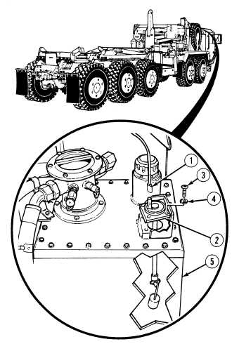
20-15. HYDRAULIC FLUID LEVEL GAGE REPLACEMENT.
a.
Removal.
NOTE
Connector is removed by gently
prying on tab and pulling
connectors apart.
(1)
Disconnect connector (1) from fluid level
gage (2).
(2)
Remove four screws (3) and lockwashers (4)
from fluid level gage (2). Discard
lockwashers.
Handle fluid level gage with care
to avoid damage to gage.
(3)
Remove fluid level gage (2) from hydraulic
reservoir (5).
After fluid level gage is removed,
cover opening to keep foreign
matter out of hydraulic reservoir
and to prevent possible damage.
(4)
Cover opening of hydraulic reservoir (5).
|