|
| |
TM 9-2320-364-20-5
21-3
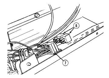
NOTE
These are two 24V relays. Both
relays are removed and installed
the same way. Refer to electrical
schematic for identification of
relays.
(3)
Remove two arctic relays (6) from relay
sockets (7).
b.
Installation.
(1)
Install two arctic relays (6) on relay
sockets (7).
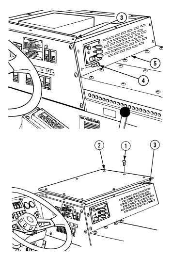
(2)
Install front heater panel (5) on heater
compartment (3) with four screws (4).
(3)
Install heater compartment access panel (2)
on heater compartment (3) with eight
screws (1).
c.
Follow-On Maintenance:
Connect batteries, (Para 7-87).
Remove wheel chocks, (TM 9-2320-364-10)
END OF TASK
|