|
| |
TM 9-2320-364-20-5
21-111
c.
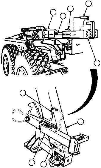
Adjustment.
(1)
Position slider in container mode
(TM 9-2320-364-10).
(2)
Raise LHS in AUTO mode approximately
18 inches (46 cm). Release joy stick (1).
NOTE
Both rear container locks are
installed the same way. Left
side shown.
Lock handle is unlocked
when facing front of slider.
(3)
Turn lock handle (2) on left rear slider
assembly (3) forward to unlocked position.
(4)
Remove lock pin (4), pin (5) and rear
container lock (6) from lifting frame (7).
(5)
Position rear container lock (6) in locked
position on left rear slider assembly (3) and
install pin (5) and lock pin (4).
(6)
Turn lock handle (2) on left rear slider
assembly (3) back to locked position.
NOTE
LHS should not move when
joystick is in unload position.
If LHS does not move in
unload position, go to Step
(14).
If LHS moves in unload
position, perform Steps (8)
through (12).
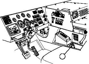
(7)
Move joystick (1) to UNLOAD position
and check LHS for movement.
STEERING WHEEL
SHOWN REMOVED
FOR CLARITY
1
2
3
4
5
6
5
4
6
7
|