|
| |
TM 9-2320-364-20-5
14-6
14-3. STEERING TOE-IN ADJUSTMENT (CONT).
NOTE
Toe-in is determined by subtracting distance A from distance B. Proper toe-in
should be 1/8 in. (1.6 mm) to 1/16 in. (1.6 mm) toe-in (B A = toe in).
If your toe-in reading is more than 1/8 in. (1.6 mm) to 1/16 in. (1.6 mm), check the
tie-rod measurement.
Tie-rods on Axle No. 1, 2 and 5 when measured from grease fitting to grease fitting should
be within the limits shown in Table 14-1.
Table 14-1. Tie-Rod Acceptable Starting Measurements
Tie-Rod
Measurement
Axle No. 1
56-5/8 in. ( 1/8 in.)
Axle No. 2
54-9/16 in. ( 1/8 in.)
Axle No. 5
51-9/16 in. ( 1/8 in.)
(6)
Determine toe-in (B A = toe-in).
NOTE
If distance is correct, toe-in
adjustment is complete: go to
Step (18). If distance is not
correct, continue with Step (7).
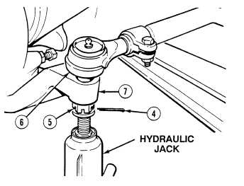
(7)
Remove cotter pin (4) and loosen castle
nut (5) even with bottom of stud on tie-rod
end (6). Discard cotter pin.
Tie-rod end may unexpectedly
pop-up when pressure is applied
with hydraulic jack. Keep hands
and face clear of tie-rod end.
Failure to comply may result in
severe injury to personnel.
(8)
Using hydraulic jack, press tie-rod end (6)
loose from steering arm (7).
|