|
| |
TM 9-2320-364-34-2
3-115
Materials/Parts
Oil, Lubricating (Item 38, Appendix B)
Tags, Identification (Item 72, Appendix B)
This task covers:
a. Removal
b. Installation
c. Follow-On Maintenance
INITIAL SETUP
Equipment Condition
Engine OFF, (TM 9-2320-364-10)
Wheels chocked, (TM 9-2320-364-10)
Rocker arms removed, (Para 3-20)
Fuel injectors removed, (Para 4-2)
Engine brake retarders removed, (Para 3-32)
Tools and Special Tools
Tool Kit, General Mechanic’s
(Item 240, Appendix F)
Caps, Vise Jaw (Item 27, Appendix F)
Gage Set, Feeler (Item 66, Appendix F)
Vise, Machinist’s (Item 248, Appendix F)
Wrench, Torque (0 to 175 lb-ft [0-237 N.m])
(Item 277, Appendix F)
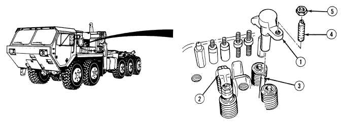
3-17. EXHAUST VALVE BRIDGE REPLACEMENT.
NOTE
Note location and position of valve bridges prior to removal.
All 16 valve bridges are removed the same way.
(1)
Remove valve bridges (1) and (2) from valve bridge guides (3).
(2)
Position valve bridges (1) and (2) in soft jawed vise.
(3)
Remove screw (4) and nut (5) from valve bridges (1) and (2).
|