|
| |
TM 9-2320-364-34-2
3-132
Materials/Parts - Continued
Tags, Identification (Item 72, Appendix B)
Gasket (Item 78, Appendix E)
Locknut (9) (Item 166, Appendix E)
Locknut (4) (Item 167, Appendix E)
Locknut (2) (Item 188, Appendix E)
Materials/Parts
Grease (Item 21, Appendix B)
Sealing Compound (Item 53, Appendix B)
Sealing Compound (Item 56, Appendix B)
This task covers:
a. Removal
b. Installation
c. Follow-On Maintenance
INITIAL SETUP
Personnel Required
Two
Equipment Condition
Engine OFF, (TM 9-2320-364-10)
Wheels chocked, (TM 9-2320-364-10)
Air system drained, (TM 9-2320-364-10)
Oil pan drained, (TM 9-2320-364-20)
Batteries disconnected, (TM 9-2320-364-20)
Left front noise panel removed,
(TM 9-2320-364-20)
Fender skirts removed, (TM 9-2320-364-20)
Brake relay removed, (TM 9-2320-364-20)
Tools and Special Tools
Tool Kit, General Mechanic’s
(Item 240, Appendix F)
Jack, Hydraulic, Hand (Item 128, Appendix F)
Jackstand (2) (Item 132, Appendix F)
Wrench Set, Socket 3/8 in. Drive
(Item 273, Appendix F)
Wrench Set, Socket 3/4 in. Drive
(Item 274, Appendix F)
Wrench, Torque (0-60 N.m)
(Item 276, Appendix F)
Wrench, Torque (0 to 175 lb-ft [0-237 N.m])
(Item 277, Appendix F)
Wrench, Torque (0 to 600 lb-ft [0-814 N.m])
(Item 278, Appendix F)
3-22. ENGINE OIL PAN AND GASKET REPLACEMENT.
a.
Removal.
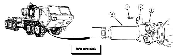
Driveshafts can weigh up to 100 lbs (45kg). Properly support driveshafts when removing
screws. After screws and brackets are removed, driveshafts can fall and may cause injury
to personnel.
NOTE
Tag and mark screws prior to removal.
(1)
Remove four screws (1) and two straps (2) from Axle No. 1 (3).
(2)
Disconnect front end of driveshaft (4) from Axle No. 1 (3).
|