|
| |
TM 9-2320-364-34-2
6-267
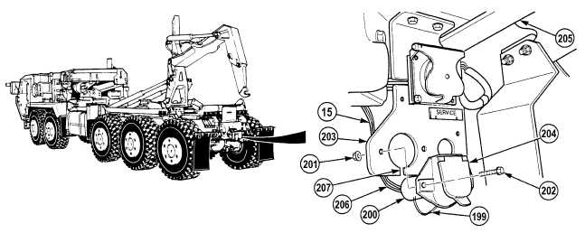
NOTE
There are two types of 7- pin electrical connectors. Model B replaced Model A.
Model A has a rubber boot covering the back.
Model B uses rubber push on connectors on the back.
Perform Step (90) for Model A connector.
(90)
Remove cable tie (199) and slide boot (200) back on chassis wire harness (15).
(91)
Remove two locknuts (201) and screws (202) from bracket (203). Discard locknuts.
(92)
Pull MC16 connector (204) toward rear of truck (205) and guide wires (206) down through slot (207) on
bracket (203).
(93)
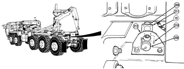
Remove cap (208) from MC30 connector (209).
(94)
Remove four screws (210), two clips (211) and MC30 connector (209) from bracket (212).
(95)
Remove chassis wire harness (15) from truck.
|