|
| |
TM 9-2320-364-34-2
9-30
9-5. AXLE NO. 3 AND 4 AXLE SHAFT REPLACEMENT (CONT).
b.
Installation.
Axle No. 3 weighs 1,780 lbs (807 kg) and Axle No. 4 weighs 1,925 lbs (873 kg). Use
jackstands to support axles. Failure to do so could result in injury to personnel.
NOTE
Steps (1) and (2) are for left side axle shaft only.
End of axle shaft with long splines goes in axle housing.
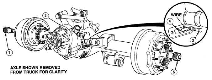
Axle No. 3 and Axle No. 4 axle shafts are installed the same way. Axle No. 4 shown.
Axle shaft is installed by aligning axle shaft splines of axle shaft with differential carrier
splines and pushing axle shaft inward and upward until axle shaft bottoms out.
(1)
Install axle shaft (5) into Axle No. 4 housing (2).
(2)
Remove screw (3) and wire from fork (4).
NOTE
Step (3) is for right side axle shaft only.
(3)
Install axle shaft (1) into Axle No. 4 housing (2).
c.
Follow-On Maintenance:
Install planetary gear assembly, (Para 9-6).
Fill axle oil, (TM 9-2320-364-20).
Install locking cylinder, (Axle No. 3 [Para 9-17]) or (Axle No. 4 [Para 9-16]) (left side only).
Install wheels/tires, (TM 9-2320-364-10).
Remove wheel chocks, (TM 9-2320-364-10).
END OF TASK
|