|
| |
TM 9-2320-364-34-2
9-66
9-11. AXLE NO. 3 ASSEMBLY REPLACEMENT (CONT).
(16)
Repeat Steps (3) through (7) and (12)
through (15) for right side air suspension
beam assembly (4).
Driveshaft weighs up to 100 lbs
(45 kg). Properly support
driveshafts when removing
screws. After screws and
brackets are removed, driveshafts
can fall and cause serious injury
to personnel.
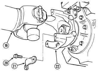
(17)
With the aid of an assistant, support
driveshaft (19) and remove four screws
(20) and two straps (21) from flange
assembly (22).
(18)
Remove Axle No. 3 end of driveshaft (19)
from flange assembly (22).
(19)
With the aid of an assistant, support
driveshaft (19) and tie driveshaft out of the
way using a cable tie.
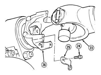
(20)
With the aid of an assistant, support
driveshaft (23) and remove four screws (24)
and two brackets (25) from flange
assembly (26).
(21)
Remove Axle No. 3 end of driveshaft (23)
from flange assembly (24).
(22)
With the aid of an assistant, support
driveshaft (23) and tie driveshaft out of the
way using a cable tie.
|